In the first article of the “The Network Society” series, I covered how the internet evolved from simple networks of sterile communication between themselves into Full Duplex communications, enabling active end-to-end communication through TCP/IP. In this second article, I will explain how one of the greatest limitations of this system came to be, why engineers underestimated the original calculation, and how that led to the (partial) collapse of End-to-End communication.
Note, however, that this article will require a greater commitment to reading the RFCs and doing additional research to understand the behavior of certain protocols. Some chapters are dense, though the examples remain simple, and some pieces may fit together better in the next article.
Internet — that is what we call it today, the TCP/IP Protocol suite. For a common user, it is enough to simply connect to a Wi-Fi network and enjoy all the data, information, and utilities it can provide, just a few clicks away. On the other side of that network, there are countless computers that are almost never turned off, that almost never sleep.
Each with its own identification number, as we discussed — IP, the protocol of each machine that allows every connected device to be located within this entanglement of connections.
The Classful Model
However, as described in the first article, machines do not connect directly to other networks. Before that, a connection to a router (or Gateway, as it is commonly referred to in the RFCs) was required. This organization can be understood as two parts: one dedicated to the network and the other to the Host wishing to use it.
To organize this structure — since at the time the number of IPs far exceeded the number of machines — the Classful model (A, B, and C) was created to organize addresses into classes.
Class A
The first class (A) provided support for a network of 8 bits and 24 bits for hosts. That means this class could support up to 16 million Hosts per network.
Due to its large host capacity at the time, it was limited to Governments, military centers, universities, and large corporations. One could imagine that even back then, it would be difficult for a company to have more than 16 million machines in its building.
Class B
The second class (B) provided 16-bit support for both the network and the hosts, meaning more than 65 thousand machines connected to the same network. It was intended for medium-sized companies, offices, and similar organizations.
Class C
The third and final class (C) provided 24-bit network support, but only 8 bits per host — common even by current standards — and was intended for the general public or small schools that would not have more than 254 hosts (or computers).
In addition to classes A, B, and C, there were also classes D and E. Class D was reserved for IPv4 multicast, enabling one-to-many communication, while Class E remained reserved for experimental use and research. These classes were omitted from the main explanation because they do not directly participate in the traditional host allocation model of classes A, B, and C. For more details on IPv4 multicast, refer to RFC 1112.
The Great Waste
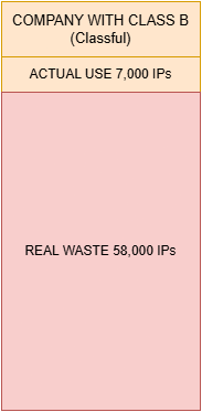
The model seemed efficient at first, but it had a serious structural problem: massive waste of IPv4 addresses. Imagine a company with approximately 7,000 employees, each using their own computer. This company would not need the absurd capacity of a Class A. However, it would also easily exceed the limit of a Class C, which only supported 254 hosts. In practice, only one option remained: receive an entire Class B.
That meant obtaining support for more than 65 thousand IP addresses, even when only around 7 thousand of them would be used. All the rest would remain unused. For example, if the fictional company Data&Courage were to receive the network 65.0.0.0/16, it could use addresses ranging from: 65.0.0.1 to 65.0.255.254.
However, if only 7 thousand machines were connected, tens of thousands of addresses would remain idle (~58 thousand addresses).
The Growth of Routing Tables
Address waste was not the only problem. As the Internet grew, backbone routers needed to store increasingly more routing information in order to know how to reach different networks scattered around the world.
These tables could contain entries such as:
65.0.0.0/24
65.0.1.0/24
65.0.2.0/24
Each entry represented an entire network. Internet routers did not need to know which computers were active within those networks. They only needed to know which path to follow in order to reach that specific network — however, the list had by then grown large enough to make them question how far it could scale before collapsing under the weight of processing. As thousands of new organizations connected to the Internet, the number of routes grew rapidly, pushing the global infrastructure toward an extremely serious scalability problem. If this problem continued, we would face endless queues, massive lists with millions of connections, some leading nowhere.
Fuller’s Working Group
Vince Fuller and his working group [2] observed another problem (beyond routing tables): with the growing number of hosts connected to the Internet, the waste of IPs had become problematic, and before long there would be an IP shortage, causing Hosts to be excluded from the network. In the words of the memorandum:
Although the memorandum was focused on resolving this problem and the growth of routing tables, it did not aim to solve the potential IP shortage. The group considered their own solution temporary until a definitive long-term idea could emerge.
And so the idea arose within Fuller’s group to create CIDR — Classless Inter-Domain Routing. The goal was twofold: remove the class system before the complete exhaustion of IP addresses, but not only that — also allow greater flexibility in IP address usage and reduce waste. Note: reduce waste — the idea here was not to effectively solve the scarcity problem, but to close the tap that had been left open for far too long.
To accomplish this, a new mechanism was needed to compensate for the Classes. The idea was essentially to allocate class numbers to each network service provider, which would then pass on bitmask-oriented subsets of the provider’s address space [2].
However, for that to work, it was necessary to understand where network identification ended and Host identification began. The Classful model delimited this boundary in a fixed manner through classes A, B, and C. CIDR, however, proposed exactly abandoning that rigidity and allowing variable-size blocks. For this, a new mechanism capable of dynamically indicating which bits belonged to the network and which belonged to the Hosts became necessary. That mechanism is the network mask.
Network Mask
The network mask is a 32-bit value used to define which part of an IP address belongs to the network and which part belongs to the Hosts. It must have exactly 32 bits in order to align correctly with IPv4 addresses, which also use 32 bits [3].
As a simple example, consider the following address:
200.10.0.0/16
Where “/16” represents the CIDR (Classless Inter-Domain Routing) prefix.
This means that:
- The first 16 bits belong to the network
- The remaining 16 bits belong to the Hosts
That is:
As described earlier, CIDR replaced the old fixed-class model (Class A, B, and C), enabling the creation of more flexible networks and reducing IPv4 address waste. With the new model, it became possible to define networks of specific sizes using different numeric prefixes, such as:
/19, /20, /21, /22, /27
Each value represents a distinct number of bits reserved for network and Hosts.
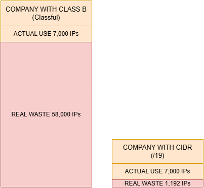
For example, a company that needs approximately 7,000 Hosts would not have to use a Class C (insufficient) nor an entire Class B (excessive waste). With CIDR, it is possible to calculate a more appropriate block.
Using a /19 prefix:
Resulting in:
This way, the network would accommodate up to 8,192 addresses, with significantly less waste (1,192 IPs) compared to the classful model. Later I will say more about how those “wasted” Hosts can be put to use.
CIDR prefixes are dynamic and vary according to the network's needs. In this example we use "/19" only as a practical reference, but any other valid value could be used, such as "/14", "/22", or "/27".
Converting the Mask
A “/19” prefix means that:
- 19 bits are reserved for the network
- 13 bits are reserved for Hosts
Converting this prefix to decimal notation, we get the following mask:
255.255.224.0
This conversion is done by representing:
- Network bits with the value
1 - Host bits with the value
0
The binary representation of /19 will be as follows:
Converting each binary octet to decimal:
11111111= 25511111111= 25511100000= 22400000000= 0
Resulting in:
255.255.224.0
The network mask allows computers and routers to determine:
- Which part of the address identifies the network
- Which part identifies the Host
- Whether a device belongs to the local network
- Or whether traffic should be forwarded to another network through a Gateway
This distinction is fundamental for understanding the concepts of local network, public network, private IP, and the IPv4 address reuse mechanisms we will see next.
Reusing IPv4 Space
If we learned anything related to Classful, it is that IP waste is truly regrettable — and that is because when it comes to IPv4, the number of addresses is limited. CIDR limited that waste, as shown in the previous example. However, there still seems to be some waste left: in the previous chapter, approximately 1,192 IPs were unused, which can be reclaimed.
There is a good explanation of how this reclamation works in Chapter 5 of Andrew Tanenbaum’s book (Computer Networks 5th Edition) [4]. However, I will condense that explanation, briefly, with a simple analogy. Let us say the fictional company SourceMobile has requested approximately 256 IPs for its machines. They certainly will not need much more than that, so they receive an address like this:
192.168.0.0/24
If we do the math:
The range between the IP they received (192.168.0.0) and the maximum they can use within this block is: 192.168.0.0 to 192.168.0.255. This occurs because, in a /24 mask, the first 24 bits represent the network, while the last 8 bits are reserved for Hosts. Thus, only the last octet can vary.
However, CIDR allows this block to be subdivided into smaller networks, as long as the ranges respect the correct binary alignment of the mask used.
Subdivision into /26
For example, we can divide this /24 into multiple /26 networks:
192.168.0.0/26
192.168.0.64/26
192.168.0.128/26
192.168.0.192/26
Each /26 block has 64 addresses. That is why valid ranges must start at multiples of 64, not multiples of 24. This means something like:
192.168.0.72/26
would not be a valid network address for a CIDR /26 block, as it breaks the binary alignment expected by the mask (remember: multiples of 64).
192.168.0.128/26 would be valid in our example. In this example we use multiples of 64 because, since we are using /26, we can calculate:
So for each new address block, a new interval of 64 must be respected. This happens because an IP cannot be allocated individually within CIDR — they are allocated in mathematically aligned blocks according to the mask used. For this reason, valid values for /26 networks would be:
192.168.0.0/26
192.168.0.64/26
192.168.0.128/26
192.168.0.192/26
Why /26 and not /19?
You might ask: why /26 and not any other value, such as /19? We use this value because we are subdividing the unused addresses within a /24 network. Since a /24 block has:
the new block must remain within that original range. If we used a smaller mask, such as /19, the resulting block would be much larger than the /24, completely overflowing the available space:
That would generate excessive subdivisions and increase the number of routing operations required. Therefore, CIDR seeks to balance the use of available space, the number of Hosts required, and the efficiency of routing.
You can think of this subdivision as partitioning a hard drive. We have the space already allocated and the space not yet allocated. Unfortunately, we do not buy hard drives that exactly match our needs. The market works with standardized sizes, so there is almost always some leftover space. That remaining space can be subdivided and reused later for other users or services with smaller needs. CIDR works in a similar way. A large block of IPv4 addresses is delivered to a provider, which then subdivides that space into smaller blocks according to each customer's needs. So a customer who needs approximately 500 addresses does not have to receive a massive block and waste thousands of IPs. The provider can supply only an appropriate subset of that larger space. For the end customer, this entire process is practically invisible. They simply receive a block compatible with their needs, while the rest of the space remains available for new subdivisions and reuse.
The Hole in CIDR
The so-called “Hole” does not occur through any specific technology. It is simply a consequence of the addressing scheme used by CIDR itself. If part of the main block is occupied by smaller networks while another part remains free, that unused space becomes a “hole” within the original block.
In addition, the CIDR system always prioritizes the most specific route. This mechanism is known as Longest Prefix Match (I will cover this in another article, as it deserves one of its own).
For now, accept this: the more precise the network mask, the higher its priority during routing. If you have a route “12.5.0.0/19” and another route “12.5.10.0/24”, the more specific route “/24” will take precedence, “punching a Hole” through the broader route.
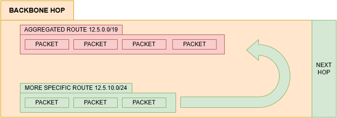
So a smaller, more specific network can “carve out” part of a larger network, causing certain packets to be directed to it instead of the broader route. It is precisely this behavior that produces the effect informally known as a “hole” within the routing table. This seems really complex, but imagine the following situation:
IANA (Internet Assigned Numbers Authority) maintains the list of IPv4 addresses not yet allocated. This is necessary to avoid conflicts between IP addresses, as explained in the previous article.
From there, IANA passes large blocks of addresses to RIRs (Regional Internet Registries), organizations responsible for the regional distribution of those addresses.
In Latin America and the Caribbean, for example, this responsibility belongs to LACNIC. Operators and network providers receive these blocks from the RIRs and proceed to distribute them to customers, companies, and smaller networks.
However, they no longer distribute IPs in isolation, but rather in CIDR-oriented blocks, such as: 12.1.0.0/16 From this main block, the operator can subdivide the available space into smaller networks, according to each customer’s needs:
12.1.0.0/24
12.1.1.0/26
12.1.1.64/26
12.1.2.0/27
And so on. This allows for a much more efficient use of IPv4 addresses, reducing waste and avoiding the mass distribution of enormous blocks to small networks.
The IPv4 Shortage, Public IP and Private IP
Even with the brilliant work of Fuller’s group, which managed to drastically reduce and reallocate wasted IP addresses, the Internet and the community at large were still on the brink of a total IP shortage.
The initial calculation did not anticipate that the Internet would be adopted as a global mechanism for communication, streaming, networking, work, and more.
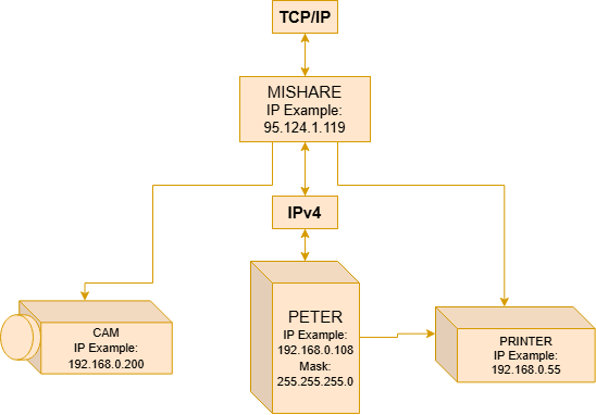
With the advent of smartphones, network-connected cameras, and the widespread adoption of personal computers, the number of available IPs began to shrink drastically. A university might use 200 IPs for its computers, while those same students would have phones that needed IPs, and computers at home that needed IPs as well. If every member of a family owned a phone, each phone would need a new IP — printers and other devices too. Soon the number of machines would surpass the number of people, which had already surpassed the available IP range.
It was not a rough estimate — it was clear that there would not be enough addresses for everyone, and potentially billions of people would be left without Internet access [5].
To address this problem, even if only as a stopgap, the Internet engineering community reached a consensus: we could split addressing into two layers — IPs that connect directly to the Internet and IPs used only for local communication. Not every device connected to a network actually needed to be reachable from the Internet, and this quickly became evident.
However, even within a local network, those devices still needed unique identifiers for internal communication. And so the separation between public IPs and private IPs emerged. Public IPs are addresses routable on the global Internet.
They must be unique and are distributed by organizations such as the Internet Assigned Numbers Authority and the RIRs (Regional Internet Registries). Private IPs, on the other hand, belong exclusively to the local network. They are not directly routable on the public Internet and can be reused across different networks without causing global conflicts.
For example, millions of networks around the world can simultaneously use: 192.168.0.1 without any problem, because these addresses remain isolated within their respective local networks. This is only possible because RFC 1918 [5] defined ranges reserved exclusively for private use:
10.0.0.0/8
172.16.0.0/12
192.168.0.0/16
This way, local devices can communicate internally using private IPs, while Internet access occurs through a shared public IP.
Of course, when using private IPs, it is worth noting that switching to a public IP would require manual reconfiguration of the machine — which can be a clear disadvantage compared to a public IP, which communicates with both the Internet and the local network.
However, for most people this does not represent a considerable disadvantage. Take Peter as an example: after receiving Anne’s image (previous article), he might decide to print it. He will use a printer connected to the LAN, with a private IP address. The fact that the printer is not accessible from the public network (Internet) becomes, for him, a benefit and a security feature.
The Imminent Collapse and the NAT Solution
The solutions presented — CIDR and the separation between public and private IPs — are considered stopgap measures, meaning they temporarily resolve a problem until a definitive solution emerges.
However, even with these measures, the number of IPs began to decrease drastically. As people used an increasing number of personal computers, the shortage predicted for some years ahead seemed to be approaching faster and faster. In this scenario, K. Egevang published a memorandum [6], proposing what he believed could complement CIDR — or even replace it.
The solution he described was an IP Network Address Translator, known as NAT. Its main advantage? It can be installed without modifying the router or the Hosts that depend on it — that is, centralization of the problem.
The Disadvantage of NAT
Its main disadvantage is the elimination of End-to-End routes, as a trade-off for increasing or preserving IPs on the network. There are at least two main types of NAT.
To begin, we will explain the first type, simply called NAT, typically installed at the edge of a LAN network. It works by translating packets between private IP addresses and a single public IP address. Think of it like this: instead of distributing a public IP to every computer on the network, operators distribute only one public IP to the NAT router, while computers, printers, cameras, and phones continue to use private IPs within the local network.
At first glance, this seems like a problem. Since these devices only have private IPs, they are not directly accessible from the public Internet. In fact, only the NAT has a real, Internet-routable public IP. All other Hosts on the local network remain “hidden” behind it.
How Anne Reaches Peter
But then how does Anne manage to reach Peter on the Internet? The answer is translation.
Let us say Anne wants to send a photo to Peter again. Anne also has a private IP, and her computer is technically offline (without direct Internet access) — but these details are of no interest to her.
Let us assume Anne is using a fictional image-sharing service (PicShare). When sending the image, Anne’s router will fragment the data packet (image) into pieces and use NAT, still within a private connection, between the data packet and the router.
From the router, we gain access to the public network. The router knows the packet belongs to Anne because it received it through her computer’s private IP (192.168.0.124).
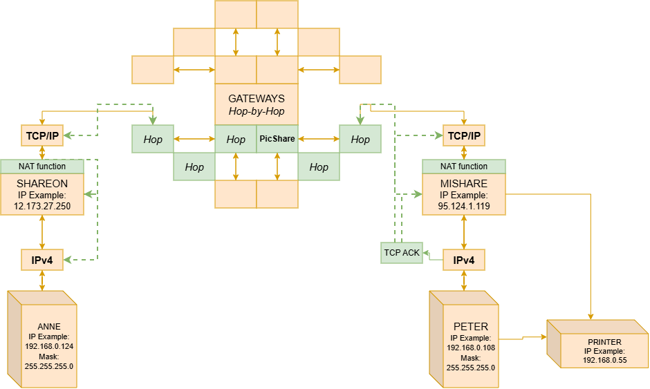
So the router uses a NAT function, registering that IP 192.168.0.124 (Anne) on port 3020 wants to send fragment Part-1 to IP 136.157.81.0 (PicShare’s server) on port 5030. The NAT records this in an internal table.
It then replaces Anne’s private IP with its public IP (12.173.27.250), and from there redirects the Part-1 packet to the destination IP 136.157.81.0:5030. It is important to note that not only the IP is replaced, but the port as well. The NAT substitutes Anne’s original port with a temporary port (1800), as a security measure.
The packet fragments are sent to the PicShare server’s public IP, and from there they can be forwarded to Peter. For the PicShare server, the packet did not come from Anne’s private IP — it has no way of knowing that — it came from her router’s NAT IP 12.173.27.250:1800.
NAT is not a specific piece of hardware. Initially it was software installed on a machine that served providers and managed the lists. However, it is now integrated into the Gateway — known as the home router — in the form of a function and protocol. In a future article I will explain more about the Router. It is important that you accept the concept as it was in its era in order to understand current and future routing technology concepts. Also note that the ports and IPs are fictional and serve only as illustrations. Some concepts have been omitted here to be explained later, such as DHCP.
It would not be inaccurate to say that after the expansive growth of the Internet — websites, smartphones, IoT devices, and others — having a single public IP per household seemed insufficient. By the 2000s, the number of computers was beginning to exceed the number of individuals. Internet providers and the Internet community faced a new challenge: how to accommodate so many people with so many machines? By that point, IPv6 was already in the process of adoption and implementation (we will discuss IPv6 in other articles in this series). However, the entire Internet infrastructure was still on IPv4 and could hardly be automatically replaced at low cost. So another stopgap solution emerged. Note that all of these solutions are stopgap measures — though some are still implemented to this day. Can they still be called stopgap? The solution was to use a second layer of NAT. The so-called Carrier-Grade NATs (CGNs) could be added at the first layer, turning the public IP of the NAT router into a private IP, thus allowing a single public IP at the first layer — which could then be used by countless subscribers. For example, there could be 50 thousand users (NAT) behind a single CGNAT, all sharing one public IP address, with each of those 50 thousand users having computers, televisions, cameras, and phones with private IPs, in a NAT -> CGNAT connection that would handle the address translation and packet listing [7].
You may have noticed that ports are varied but not unlimited. Note that ports in this structure end up functioning as values complementary to the IP. This means that a CGNAT ends up managing a large number of ports (~65 thousand ports). If the CGNAT has a large number of NATs issuing requests and commands, there may be exhaustion of those ports — Port Exhaustion — and the provider will likely reset those ports to prevent connection failure, or configure a timeout for inactive connections. I will discuss the most common ports and other protocols in another article in the series.
Conclusion
In the first article of The Network Society series, I covered how we went from sterile external connections to having End-to-End communication, the creation of TCP as a protocol, and the emergence of IP. We traced the complete path with Hop-By-Hop, analyzing the traffic between Anne and Peter.
In this second article, I addressed the limitations of IPv4, the classes and their problems, and the endless layers of stopgap solutions that not only added complexity but also solved problems of security, scalability, and network management. The whole project was not architected all at once, but rather carefully developed as the network’s needs evolved.
We followed how, before Anne’s packet reaches Peter, it must pass through a NAT, which uses a single public IP — transforming Anne’s private IP into a completely different one, with a temporary port — before being forwarded to the server, from where it can reach Peter.
We also saw how Anne’s IP receives a network mask, how it is calculated, and what it is used for. But this is not all — there are still many unanswered questions from the first and second articles that we will address. How does Anne’s router know her computer’s private IP? How does Peter’s computer know which machine is his within the local group list? And, do Anne and Peter really need to memorize private and public IPs every time?